How Anyline Works
|
Outdated Information!
|
This section describes the central integration-facing elements of the Anyline SDK and how the components work together to build scanning use-cases in your application.
| Read through this section before jumping into the integration of Anyline to get a conceptual understanding of how everything works and what possibilities you have in your use-case. |
Basic Information & Concept
The main purpose of the Anyline SDK is to perform OCR (optical character recognition) in order to capture data on-device from the camera in real-time. This data can be used for multiple purposes - such as user guidance & augmentation.
The following image is a depiction of what the user will see when integrating Anyline.

|
|
There are many variables to consider when integrating Anyline. Some relate to the look & feel of the scanner while others relate to constructing and fine-tuning the scanner itself in order to optimize the quality of the data capture.
To meet these requirements, the SDK consists of multiple components, which can be easily configured.
Components
Here’s a high-level overview of the most important SDK components:
-
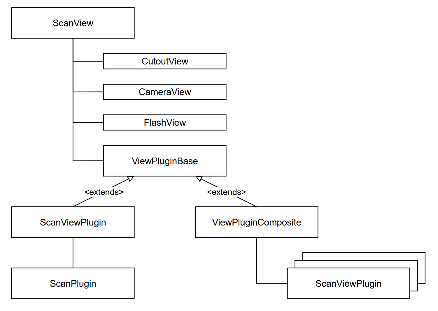
ScanView
-
The
ScanViewis the top UI element, which extends aWindows.UI.Xaml.Controls.Gridand thus can be directly placed in your Page. It is configured with aScanViewConfig.
-
-
CutoutView
-
The
CutoutViewis responsible for rendering any scanning visualization, such as visual feedback and Cutouts. "Cutout" is what we call the region inside the area that shall be scanned. It is configured with aCutoutConfig. -
This component is not directly accessible via code and only shown here for explanation purposes.
-
-
CameraView
-
The
CameraViewis responsible for accessing, starting and rendering the camera preview. It is configured with aCameraConfig. -
Internally, the camera controls frame broadcasting to any plugin that is connected to the
ScanView.
-
-
FlashView
-
The
FlashViewtakes care of rendering the Flash button and is configured with aFlashConfig.
-
-
ViewPluginBase
-
The
ViewPluginBaseis the abstract base class of an element that connects scanning logic with the view logic, hence the name. -
There are currently two types of view plugins - one for composite scanning and one for single scanning.
-
-
ScanViewPlugin
-
The
ScanViewPluginis the glue that connects an actual scanner with the view and is configured with aScanViewPluginConfig. -
A
ScanViewPlugincontains aScanPluginand directs data from the view to the scanner and back.-
The visible cutout gets translated into the ROI (region-of-interest) of the attached
ScanPlugin. -
Certain events from the
ScanPluginare being used to update the views, for example visual feedback and brightness information for the torch.
-
-
-
ScanPlugin
-
The
ScanPluginis the scanning element that processes image data and delivers information through events that can be further processed. It is configured with aScanPluginConfig.
-
-
ViewPluginComposite
-
The
ViewPluginCompositecan be used to set up a scanning workflow that consists of multiple different scanners in a parallel or sequential manner. -
This is useful for capturing different kinds of data at once or within a structured workflow.
-
|
Resources, Initialization & Destruction
Most elements are designed to be only constructed with a given configuration and cannot be changed once they are initialized.
|
Configurations
This is a brief overview of how the configurations work together and what their purpose is:
-
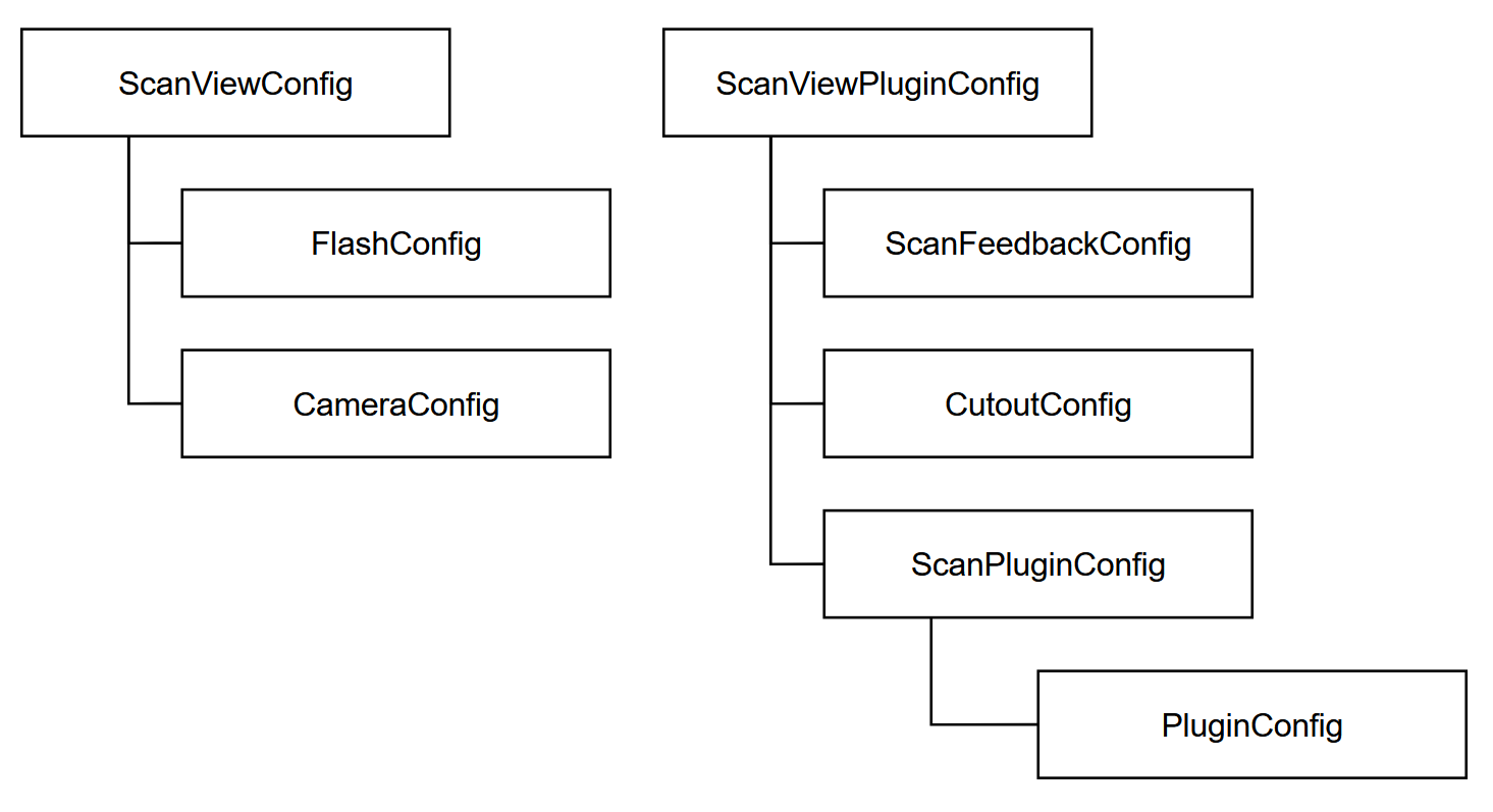
ScanViewConfig
-
The
ScanViewConfigcontains the necessary configurations for theScanViewitself.
-
-
FlashConfig
-
The
FlashConfigsets parameters like flash mode & alignment of the flash button.
-
-
CameraConfig
-
The
CameraConfigsets parameters like the resolution and which camera to prefer when the device offers multiple cameras.
-
-
ScanViewPluginConfig
-
The
ScanViewPluginConfigcontains all necessary parameters and configurations to set up aScanViewPlugin.
-
-
ScanFeedbackConfig
-
The
ScanFeedbackConfigdetermines what kind of feedback to visualize amongst other parameters (like playing a beep-sound or blinking upon a successful scan).
-
-
CutoutConfig
-
The
CutoutConfiglets you set up where to place theCutoutand adjust parameters like it’s size, ratio and color.
-
-
ScanPluginConfig
-
The
ScanPluginConfigserves as a wrapper for thePluginConfig, highlights important parameters like the plugin ID and whether the plugin should stop scanning upon receiving a result.
-
-
PluginConfig
-
The
PluginConfigcontains the configurable parameters of all supported scanning capabilities and is used to set and fine-tune what you want to scan.
-
|
PluginConfig & PluginResult
The scanning capabilities are designed so that each type of
You can only set up one type of scanner per PluginConfig - If you want to scan multiple different objects, please refer to using a |